2. Power Supply for Photo Webcam
- Daniel Baertschi
The power supply simplifies powering up camera and additional equipment and eliminates the cables tangling. The power supply is designed for long-term operation in extreme temperatures.
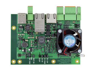
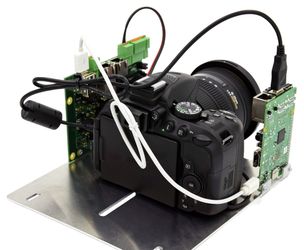
Picture: Power supply for Photo Webcam and wiring guide.
Quick start guide
Which voltage does my camera need?
The power supply is suitable for cameras with a battery voltage of 3.6, 5, 7.2 or 12 VDC. Before connecting, please check the battery voltage of your camera, the output voltage of the battery charger and the camera manual. Please be careful with the polarity. In case of doubt, please ask an expert..
Attention
No liability is accepted for any damage.
- Camera voltage 4VDC
Does your camera battery show a voltage of 3.6VDC? Is an output voltage of 4.0-4.2VDC referenced on your battery charger?
→ Use a 4VDC for “Power supply for Photo Webcam” if the voltage of your battery and your charger is between the limits mentioned above. - Camera voltage 5VDC
Connect the camera with P7 USB or O6 5VDC if your camera is typically charged with USB. - Camera voltage 8VDC
Most DSLR-cameras and SLT-cameras have a battery voltage of 7.0-7.4VDC. The relevant battery chargers reference an output voltage of 8.0-8.4VDC.
→ Use 8VDC if the voltage of your battery and your charger is between the limits mentioned above.
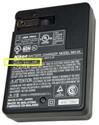
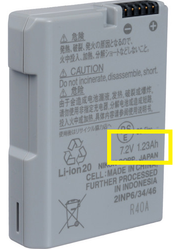
Picture: Voltage battery charger and battery
No battery is provided for the camera’s voltage supply. Use the appropriate battery adaptor for the voltage supply. For the configuration of the corresponding output voltage, please use Jumper JP4. Check the polarity before you connect the camera.

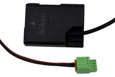
Picture: Camera wired, typical battery adaptor for external voltage supply for the camera
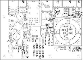
Standard settings for operation
| Description | JP1 | JP2 | JP3 | JP4 | JP5 | JP6 | JP7 | JP8 | JP9 | JP10 | JP11 | JP12 |
|---|---|---|---|---|---|---|---|---|---|---|---|---|
| 8 VDC camera, power supply Passive PoE / 12.5-56 VDC, with (additional) heater | - | Yes | - | - | ON | ON | EXT | Yes | Yes | Yes | Yes | Yes |
| Solar power with night-off, power supply via P2, without heater | - | Yes | - | - | ECO | ECO | EXT | - | Yes | Yes | Yes | Yes |
Typical configurations
| Configuration | Jumper / Plug |
|---|---|
| Passive PoE or 12.5-56 VDC input voltage via P2 | JP2 closed JP3 open |
| PoE+ voltage supply | JP2 open JP3 closed |
Automatic switch-off of the voltage at night | For 12 VDC: JP5 on position ECO closed for 5V and camera voltage: JP6 on position ECO closed |
Heater and ventilation from power supply board | Always JP8 closed |
External heater via Plug P1 | JP7 open JP7 closed in position Temp JP7 closed in position Ext |
| Sleep Mode controllable via P2 12 VDC controllable Camera voltage controllable 5 VDC controllable | JP12 closed JP9 closed JP10 closed JP11 closed |
| Adjust camera voltage 3.6 - 4 VDC 7.2 - 8 VDC | JP4 closed JP4 open |
| All LEDs switched off | JP1 open |
Detailed configuration and specification
Output voltages
| Plug | Voltage (output) |
|---|---|
| P1 | 12 VDC for front glass defroster heater |
| P2 | Input voltage provides supply voltage (parallel output) |
| P3 | 4 VDC / 8 VDC for camera (can be chosen with Jumper JP4) |
| P6 | 5 VDC / 12 VDC for camera or additional devices |
| P7 | 5 VDC from USB plug (no USB Signal only voltage supply) Safeguarded with 2A. |
Input voltage and supply
| Plug | Voltage (input) / control signal |
|---|---|
| P2 | 12.5 - 56 VDC voltage supply * |
| P2 | Control input. On / Off output voltage, e.g. Sleep Mode with solar power |
| P5 | via RJ45: Power over Ethernet PoE+ 802.3at to 56VDC / 25.5 watt or Passive PoE 12.5 - 56VDC (see Passive PoE Injector) |
| P8 | Input to activate output voltage P1 for front glass defroster heater |
| Photodiode | Light sensor for automatic day / night control of output voltages |
* To guarantee a 12VDC output signal, the input voltage has to be between 12.5 and 56VDC. If 12 VDC output voltage is not required, a lower supply voltage can be used. The voltage drop because of the power supply is around 0.5 VDC.
Plug Pin Occupancy
| Plug | Pin | Signal |
|---|---|---|
| P1 | 1 | 12VDC output for front glass defroster heater |
| 2 | Ground GND | |
| P2 | 1 | Input 12.5-56VDC for external voltage supply of the whole board. Alternatively, it is possible to provide the supply voltage over P5 and PoE+ or passive PoE. |
| 2 | Input Ground GND | |
| 3 | Output VDC. Provides the input voltage that is connected to P2 Pin1. | |
| 4 | Output Ground GND. For use with P2 Pin3 | |
| 5 | Control input. To deactivate output voltage, place 0VDC. Configuration - see Jumper JP9-JP12. | |
| 6 | Control input Ground GND. For use with P2 Pin5 and Pin7 | |
| 7 | Control input. To deactivate output voltage, place VDC. Configuration see Jumper JP9-JP12 | |
| P3 | 1 | Output voltage 4VDC or 8VDC for camera. Default: for 8VDC no Jumper JP4 closed. For 4VDC cameras, close JP4. |
| 2 | Output Ground GND for camera | |
| 3 | Optional connection for buffer capacitor if using a professional camera. | |
| 4 | Connection Ground GND for buffer capacitor | |
| P4 | RJ45 | LAN-connection for camera controller. The Ethernet signal is passed on transparently in both directions between P4 and P5. |
| P5 | RJ45 | Input voltage supply and data connection. P5 can be configured with configuration of Jumper JP2 and JP3.
|
P6 | 1 | Output voltage 12VDC for additional devices |
| 2 | Output Ground GND for auxiliary devices | |
| 3 | Output device 5VDC for additional devices | |
| P7 | USB | 5 VDC for additional devices. Important: this USB connector supplies no USB signal and is only suitable for voltage supply of additional devices. |
| P8 | Control input for front glass defroster heater. |
Important: The Pin Occupancy is also inscribed on the board.
Specifications
| Input | Voltage | max. current | max. power |
|---|---|---|---|
| Voltage supply P2 | 12.5 - 56 VDC | <4A | typ. 50.0 watt |
| Voltage supply P5 | PoE+ 802.3at | - | 25.5 watt |
| Voltage supply P5 | Passive PoE 12.5 -56 VDC with 12.5 VDC | <0.7A | 35.0 watt 67.0 watt |
| Total maximum power | All voltages together | 87.5 watt | |
| Camera voltage | 4 VDC / 8VDC | 3.5A | 28.0 watt |
| Additional voltage | 5 VDC all exists incl. USB | 3.5A <2A | 17.5 watt |
| Additional voltage | 12 VDC incl. heater | 3.5A | 42.0 watt |
| Onboard extractor fan | 12 VDC | 0.11A | 1.32 watt |
| Onboard heater | 12 VDC | 0.48A | 5.76 watt |
Operating temperature: -40°C to +75°C
Important
To reach the maximum output power of 87.5 watt chose an input power from 24VDC via P2 or 48VDC via P5.
Backup Capacitor
Depending on the power requirements for the camera, you can connect a backup capacitor on plug P3 Pin 3+4 to stabilize the voltage parallel to the output voltage. This operating mode is only supported with Passive PoE or 12.5 – 56 VDC voltage supply. Type of capacitor: AL-Elko, Specification: max. 47'000 uF / 10 VDC.
LED-Display
All LEDs are exclusively used to display the active output voltage. The corresponding LED shines if the voltage is activated. To avoid annoying light reflections, switch off the LEDs for operational use with Jumper JP1. Please remove the Jumper in this case.
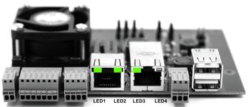
LED1: 5VDC Output voltage active
LED2: Camera supply voltage 4VDC / 8VDC active
LED3: 12VDC output voltage active
LED4: not used
Cabling external heater
See 5. Frontglas Defroster Heater
Assembly
The power supply board can be mounted direct and without insulators on the mounting plate..
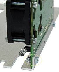
Picture: Assembly of power supply board on mounting plate
Solar power
The equipment power supply is suitable for direct operation with solar power or battery. For this you can connect P2 direct with the solar Panel <56VDC or battery. If no 12VDC voltage for additional devices is needed, you can also connect a lower voltage with P2.
Important
The voltage drop between input voltage at P2 and the output voltage is at least 0.5 VDC. If the supply voltage is lower, maximum power is reduced corresponding to the supply voltage. The maximum output power depending on voltage is 3.5A. The maximum input powers of P2 must not exceed 4A and on P5 2.88A. If the voltage supply is lower than 12VDC, the PoE+ Injector could be useful. The PoE+ Injector provides already from 5VDC PoE+ with max. 25.5 watt.
Dokumente
Power Supply for Photo Webcam V3_3.pdf